Circuit Configuration - 1 Channel
The following is a simple circuit diagram for a single pressure sensor.
| 
|
Output value formula:
	Vout = Vin × R2/(R1+R2)
	R1: The resistor closer to Vin in the diagram above. R2: The resistor closer to GND above.
Rising type circuit characteristics
- Initial state Vout is 0. Vout increases as more pressure is applied.
- No power consumption when no pressure is applied.
- Can be configured as a GPIO Wakeup circuit.
Falling type circuit characteristics
- Initial state Vout is close to ADC maximum (but not at maximum). Vout decreases as pressure is applied.
- Circuit is electrically more stable.
Graph Slope Variation by Rc Value
The following applies to rising type circuits.
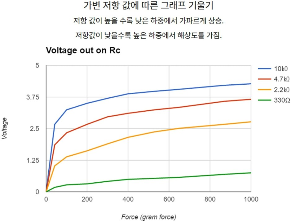
▲ Figure: Graph slope by Rc value
- If the Rc value is too high, most of the ADC resolution is consumed at initial loads.
- For Marveldex sensors, we recommend setting the Rc value to 0.5K~2Kohm.
Product for finding the appropriate Rc value: 'Pressure Sensor Starter Kit - 4 Channel'
Output Stage Stabilization
To reduce noise, you can connect a capacitor between the Vout output and ground. (Typically recommended: 1nF~10nF) The higher the capacitor value, the more noise is reduced, but the signal is reflected more slowly, which may make the sensor response feel slower.