What is an FSR Sensor?
What is an FSR Sensor?
FSR stands for Force Sensitive Resistor. It has the characteristic of decreasing resistance when force is applied. In electrical circuits, it is classified as a variable resistor.
Structure and Principle of FSR Sensors
This is the basic structure of a pressure sensor. It consists of an upper plate and a lower plate.

▲ Basic structure of an FSR sensor
- Upper plate - A piezoresistive element whose resistance decreases as more pressure is applied.
- Lower plate - Acts as an electrical substrate.
- Spacer - Located between the upper and lower plates, consisting of an adhesive layer with an open center. The upper plate must be pressed within this open area for proper operation.
This is the basic structure, and exterior materials may be added for sensitivity adjustment and durability enhancement.
Circuit Configuration of FSR Sensors
FSR sensors are typically measured through an ADC (Analog-to-Digital Converter) circuit.
Basic Circuit Configuration
- The sensor consists of two terminals(pads).
- Apply voltage to either terminal, and connect the other terminal to the ADC.
- Adding a pull-down resistor is recommended for signal stabilization.
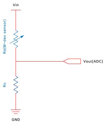
▲ [Figure: FSR sensor circuit configuration]
- Typically apply voltage between 1.5V and 12V.
Force-Resistance Graph
Resistance output is inversely proportional to applied pressure.
Below is an example graph showing the relationship between sensor pressure and resistance values(Blue). The blue line represents the resistance curve. The red line represents the inverse of resistance, which corresponds to the ADC terminal output.
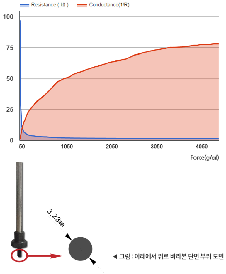
[▲ Output variation of FSR sensor by pressure level (Marveldex RA18 sensor)]
Summary of FSR Sensor Characteristics
- ✅ Simple structure: Two-layer construction.
- ✅ Operating principle: Resistance changes inversely with load (= voltage changes proportionally with load).
- ✅ Usage: Select a sensor with a range appropriate for your primary load application.